Hardware
Three documents sit underneath this library. Every timing constant, pin limit and register offset in the code came out of one of them, so when the code and the silicon disagree, these are what settle it.
Documentation
ESP32-S3 datasheet
Espressif · PDFThe chip itself: every pad and the IO MUX functions it can take, absolute maximum ratings, current draw per power mode, and the package drawing. Reach for it when you need to know what a pin is allowed to do rather than how to make it do it — gpio_config_output() asks for roughly 20 mA of drive, and this is where the ceiling on that number is written down. Note what is not here: the register addresses and bit fields this library pokes live in the Technical Reference Manual, a separate and far longer document.
What it explains here: regs.h
XL-0807RGBC-WS2812B LED datasheet
Waveshare · PDFThe addressable RGB LED soldered to the board, on GPIO21. It has no clock line: each bit is a high pulse whose length decides whether it reads as a zero or a one, which is why the driver bit-bangs it against the cycle counter. The five timing constants at the top of esp32s3/src/led.c — LED_T0H_NS and its neighbours — are transcribed from the table in here, and it is the first thing to check if a strip bought elsewhere refuses the same signal.
What it explains here: led.c
ESP32-S3-Zero wiki
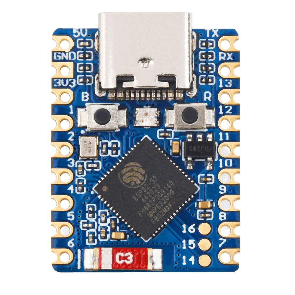
Waveshare · WikiThe board rather than the chip: which pads actually reach the castellated edge, where BOOT and RST are, and the fact that the single USB-C port is the chip's own USB-Serial-JTAG rather than a bridge chip — which is why flashing and the console share one cable and no auto-reset circuit exists. Two constraints worth reading before choosing pins: GPIO33–GPIO37 are wired to the PSRAM and are not broken out, and GPIO19/GPIO20 are the USB data lines.
What it explains here: board_pins.h
Onboard resources
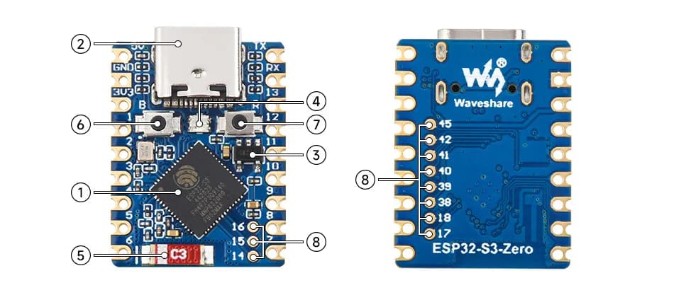
- ESP32-S3FH4R2 dual-core processorRuns at up to 240 MHz. The ROM hands it over at 20 MHz and board_init() takes it to 160.
- USB Type-C portProgram download and debugging. It is the chip's own USB-Serial-JTAG rather than a bridge chip, which is why there is no auto-reset.
- ME6217C33M5GLow-dropout regulator, 800 mA maximum output.
- WS2812 RGB LEDOn GPIO21, and the board's only LED.
- 2.4 GHz ceramic antenna
- BOOT buttonGPIO0. Hold it, tap RESET, then release to enter download mode.
- RESET button
- ESP32-S3FH4R2 pin extensionThe castellated pads. GPIO33–GPIO37 are spent on the PSRAM and never appear.